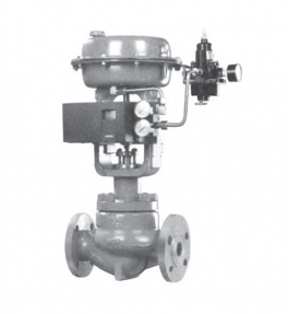
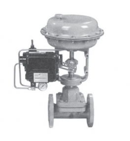
ZHPC high pressure cage regulator is one of Cv3000 series products. It can control high pressure fluids at different temperatures. It is a pressure balancing regulator. It is widely used in high pressure drop situations requiring good dynamic stability, low noise and low cavitation corrosion.
main features
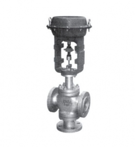
Equipped with multi spring film actuators, compact structure and high output power.
Valve structure is compact, fluid channel is S streamlined, pressure drop loss is small, flow rate is large, adjustable range is wide.
Control valve leakage meets ANSI B16.104 standard.
Main technical parameters
Valve body
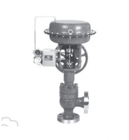
Type: straight through casting ball valve
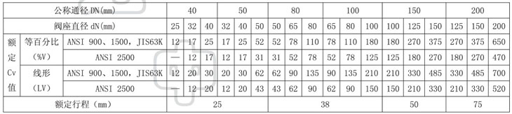
Nominal access: DN40, 50, 80, 100, 150, 200mm
Nominal pressure: ANSI 900, 1500, 2500
JIS 63K
Connection type: flange connection RF, RJ
Flange standard ANSI B16.5-1981, JIS B2201-1984 and so on.
Welding connection SW (40~80mm) for welding BW (80~200mm).
Materials: cast steel (WCB), CrMo steel, cast stainless steel (CF8, CF8M), titanium (Ti), etc.
Upper valve cover: normal temperature (P) -5 ~ +230 C
Elongation type I (E I) +230 ~ +566 C
Note: the working temperature should not exceed the allowable range of all materials.
Gland type: bolt compression type.
Packing: V type polytetrafluoroethylene, impregnated polytetrafluoroethylene asbestos, asbestos braiding, graphite packing.
0 valve components
Spool type: pressure balanced cage double seat spool
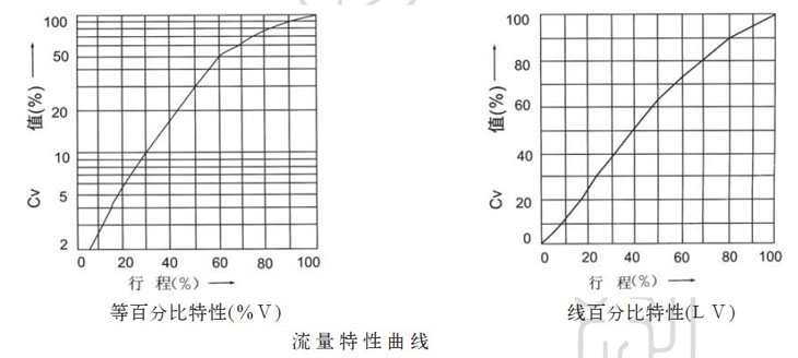
Flow characteristics: equal percentage characteristics (%V), linear characteristics (LV)
Materials: stainless steel (304, 316, 17-4PH, 9Cr18, 316L), stainless steel overlay welding alloy,
Titanium (Ti) and corrosion resistant alloys.
Executive agencies
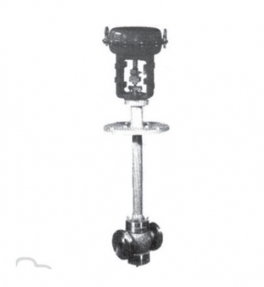
Type: LHA multi-spring film actuator, LVA5 single-spring film actuator, LVA6 single-acting cylinder piston holder
Mechanism and LVP double acting cylinder piston actuator
Diaphragm material: LHA, LVA5 type ethylene propylene rubber, nylon cloth, NBR nylon cloth.
Spring range: 40~200, 80 ~ 240kPa (type LHA, LVA5) 190~350, 190 ~ 400kPa (LVA6 type)
Supply pressure: thin film actuator LHA (280-240kPa), LVA5 (280kPa), piston actuator LVA6 (400-240kPa)
500kPa), LVP type (300 ~ 500kPa)
Air source connector: Rc1/4
Ambient temperature: -30 ~ +70 C
Valve action type: positive actuator realizes valve's gas-close type, reaction actuator realizes valve's gas-open type
Accessories: positioner, air filter pressure relief valve, stroke switch, retaining valve, valve position conveyor, handwheel mechanism, etc.
0 performance
Leakage: meet the standard ANSI B16.104-1976 grade III, less than 0.1% of the rated Cv value.
Return error: 1% with locator less than full stroke.
Basic error: + 1% with locator less than full stroke.
Note: Standard V PTFE packing is adopted.
Adjustable range: 50: 1
0 Cv value and stroke
Typical flow characteristic curves
Allowable pressure difference
I. LHA or LVA actuators for valves
A. gas shut valve 100kPa
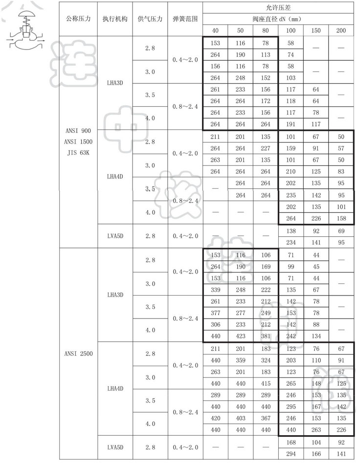
B. gas open valve 100kPa
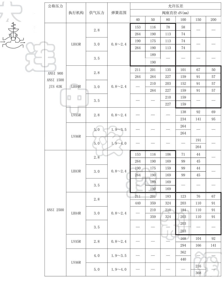
Note: P=P1(P2=0) is the condition of allowable pressure difference when the table is closed. The pressure difference at full closure varies slightly with the outlet pressure P2.
Maximum allowable differential pressure shall not exceed the maximum working pressure specified in ANSI B16.34-1981 or JIS B2201-1984 standards
The inlet pressure P1 shall not exceed the allowable pressure difference when the valve is closed.
* the number above the same grid indicates the allowable pressure difference, and the lower figure indicates the allowable pressure difference.
- digital control mechanism for digital control of valves in black frame
II. Valve equipped with LVP actuator 100kPa
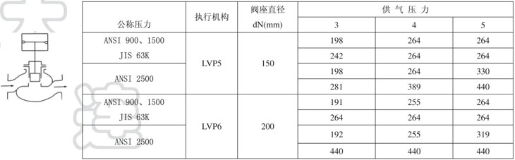
Note: If the actuator has an auxiliary gas source, the smaller one of the two should be selected as the basis for calculating the allowable pressure difference.
The condition of allowable pressure difference is P=P1 (P2=0) when the table is closed. The pressure difference at full shutdown varies slightly with the outlet pressure P2.
Maximum allowable differential pressure shall not exceed the maximum working pressure specified in ANSI B16.34-1981 or JIS B2201-1984 standards
The inlet pressure P1 shall not exceed the maximum allowable pressure difference when the valve is closed.
* the number above the same grid indicates the allowable pressure difference, and the lower figure indicates the allowable pressure difference.
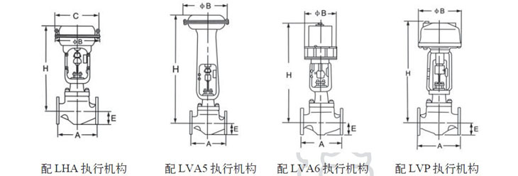
Shape connection dimension
Flange dimensions mm
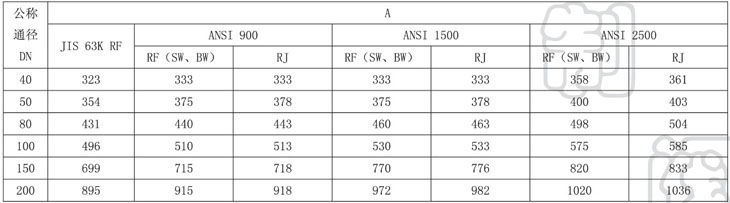
Size mm
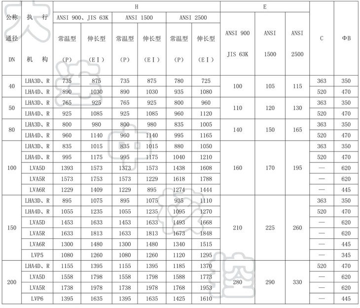
Note: The H dimension in the table is the number when the control valve is not equipped with handwheel mechanism. If the handwheel mechanism with top mounting is equipped, the size of handwheel mechanism should be added accordingly.
Weight kg
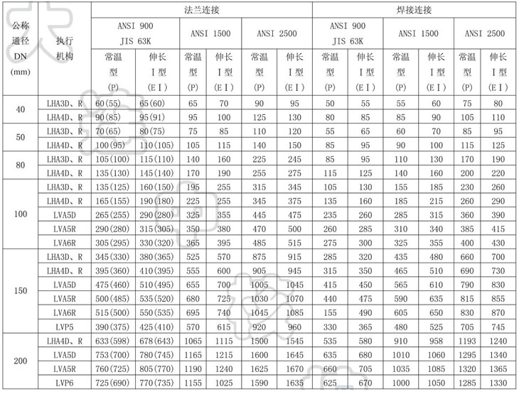
Note: the number in brackets is the weight of the nominal pressure JIS 63K valve